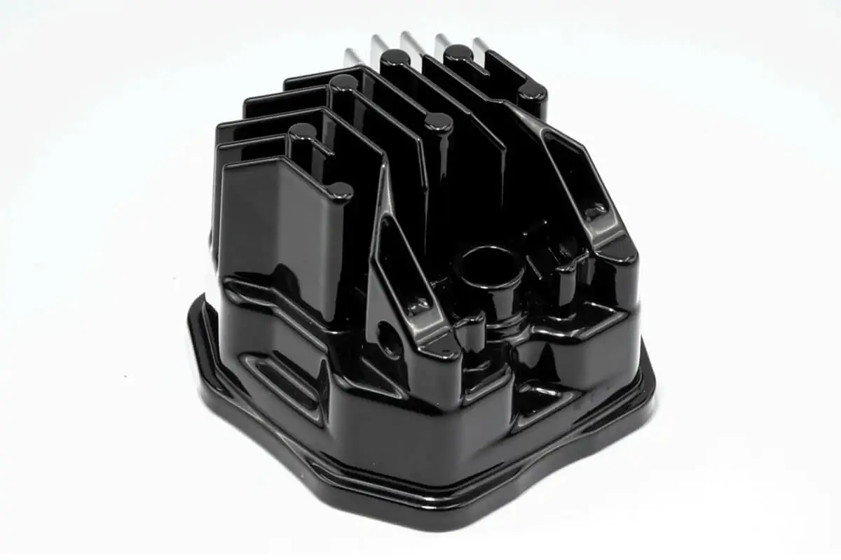
A die cast flood light housing from JoinCast is normally cast in ADC-12 / A383, with the bosses for the bracket or yoke cast in and machined where the drawing requires it. The driver compartment can be integrated or cast separately, and outdoor housings are shot blasted and coated, with salt spray testing typically run for 96 to 500 hours.
JoinCast operates a vertically integrated aluminum die casting facility in Changhua, Taiwan, and supplies major brands in the USA and Europe. LED lighting is one of the sectors we serve, and we produce die cast LED lighting housings and heat sinks for commercial floodlights, street lighting, high-bay warehouse fixtures and architectural lighting, made to our customers’ own designs. In this article we explain whether to integrate the driver compartment, what to state on the drawing, how large a flood light housing we can cast and coat, and how we finish it for outdoor service, with notes on the standards that apply in the US and European markets.
Should the driver compartment be part of the flood light housing casting?
A flood light driver compartment can be cast as part of the finned housing or produced as a separate casting, and the choice affects the part count, the size of the casting and the tooling. On heat sinks and controller enclosures, our mold engineering team can design heat sink fins integrated into the enclosure, which reduces part count and often improves thermal performance by removing the interface resistance between housing and heat sink. On a flood light, the same approach can be extended to the driver compartment, with the advantages and limits described below.
Integrating the driver compartment into the housing casting
With the driver compartment cast into the housing, the fixture has one fewer part to source, inspect and assemble, and there is no joint between the driver enclosure and the finned body. The housing does become a larger casting, however, which needs a larger machine and makes the size limits described later in this article more relevant to your design. The driver cover face and the LED mounting face then sit on the same part, and all of our CNC (computer numerical control) machines have fourth-axis capability for complex geometries of this kind.
Casting the driver housing as a separate part
A separate driver housing means two smaller tools and two smaller castings. On a large flood light, that may keep each part within our 3 kg and 700 mm range where a single casting would not. It may also allow you to use one driver housing across a family of fixtures with different optical housings, which is worth considering if you plan several wattages on one platform.
If you haven’t yet decided between the two, we would suggest including both options in your request for quotation. Our mold engineers can then comment on each before the tooling is designed.

What to state on the drawing for a die cast flood light housing
Die casting can form complex fin structures, integrated mounting features and housing details in a single shot, so the mounting features of a flood light housing belong on the drawing from the start, where our mold engineers can review them with the rest of the casting.
If your drawing calls for A383 or A360, these are the US designations for the ADC-12 and ADC-3 that we cast, as our reference on alloy names across regions shows. You can therefore keep your drawing in US designations.
The table sets out where each feature of a typical flood light housing is formed, what we would ask you to state on the drawing, and the equipment in our quality department that can check it. That equipment includes our CMMs (coordinate measuring machines) and a 3D scanner, which compares the casting with your CAD (computer-aided design) model.
| Feature on a flood light housing | Cast or machined | What to state on the drawing | Equipment that can check it |
|---|---|---|---|
| Fin array and external profile | Cast | Fin layout, fin thickness, draft and cosmetic faces | 3D scanner |
| Bracket or yoke bosses | Cast, then machined where the drawing requires it | Bore or thread size, tolerance, position and the aiming axis | CMM |
| Glass or lens frame sealing face | Machined where the drawing requires it | Flatness and the extent of the sealing area | CMM |
| LED mounting face | Machined | Flatness and the datum it relates to | CMM |
| Cable entry boss | Cast, then machined where the drawing requires it | Thread or bore size and position | CMM |
| Coated external surfaces | Cast, then shot blasted and coated | Finish system and color reference | Roughness tester before coating; spectrophotometer for color after coating |
Bracket and yoke bosses for aiming the fixture
A flood light is aimed after installation, so the bosses that carry the bracket or yoke define the pivot axis of the whole fixture. We cast the bosses into the housing and, where the drawing requires it, machine the bores or threads that locate the bracket, holding bores to H7 where that is specified. You should state the bore or thread size, its tolerance and its position relative to the housing datums, and mark which faces around each boss are cosmetic, because the CAD model alone does not show which surfaces matter to you.
When our mold engineers review your CAD files at the quoting stage, they look for heavy sections behind the bosses, because a heavy section does not cool at the same rate as the wall around it. Our article on how we review a housing drawing describes this review in more detail. Where a rib would serve as well as a heavy section, we will say so during the review, before the tool is built.
The glass frame face and the fin array
Where the drawing requires it, we machine the face that the glass or lens frame seals against. Our article on machining the LED mounting and sealing faces covers that face, the LED mounting face and what the housing contributes to your luminaire’s IP (ingress protection) rating, so we won’t repeat it here.
The fin array normally stays as cast. The North American Die Casting Association (NADCA) notes in its comparison of die casting and metal extrusion that die casting is not limited to producing parts with uniform cross sections, and a die cast flood light housing can therefore carry variable fin heights and non-linear fin arrangements. For a dense or complex fin layout, we use mold flow simulation to predict how the metal fills the fins and where porosity or cold shuts may form, before any tooling is machined. We share the report with you at the mold design review, and it is worth settling the fin layout there, since corrections after the tool is cut are expensive and slow.
How large a flood light housing can we cast and coat?
We run 12 die casting machines from 135 to 900 tons, and we cast parts weighing from 5 grams to 3 kilograms (6.6 lb), with castings up to 700 mm (27.6 in) on the 900 ton machine. Our page on our die casting machine range lists the part size for each machine.
Flood light housings between 600 and 700 mm
Our hanger shot blaster, which prepares larger parts for coating, takes parts up to 600 mm (23.6 in). A coated flood light housing between 600 and 700 mm therefore needs its finishing route agreed with us before the design is fixed. A housing longer than 700 mm or heavier than 3 kg is outside our current range, and we would rather you knew that at the start.
Within that range, our mold engineering team calculates the machine your housing needs from its projected area during quoting, as our glossary entry on machine tonnage selection explains. Please send the CAD model with your first inquiry, so that we can make the calculation before you commit to the design.
Thin fins and the finishing route
Fin thickness affects how the housing is finished as well as how it fills. Thin-walled sections below 2 mm normally receive vibratory barrel finishing rather than hanger blasting, and we would confirm with you whether that suits a large finned housing. Walls below 1.5 mm risk incomplete fill or weak sections, and typical wall sections on our castings run from 2.5 to 4.5 mm, depending on part size and flow length.
If the fins on your housing are thinner than 2 mm, please state their thickness on the drawing, as the table above suggests. It affects both the tool and the finishing route, and we can then agree with you how the housing will be prepared for coating.
Finishes and standards for flood lights sold in the US and Europe
We apply five surface treatments in our own facility: powder coating, electro-coating, liquid coating, anodizing and SurTec 650 trivalent chromium treatment. An outdoor flood light housing normally has a paint finish (powder or liquid coating), although anodizing and trivalent chromium treatment are also available.
Powder coating, liquid coating and the other treatments
For LED housings we offer powder coating for outdoor durability. Before coating, we shot blast the housing, which typically produces a surface roughness of Ra 1.6 to 3.2 μm and gives the coating a surface to adhere to, and we check the roughness on our two dedicated testers before the parts proceed to coating. Liquid coating allows custom color matching for branded products, which is useful where a flood light must match a brand color, and we check the color on a spectrophotometer.
Anodizing and trivalent chromium treatment both give corrosion resistance for outdoor equipment and comply with environmental regulations, so they’re worth discussing if your design calls for something other than a paint finish. Because every treatment runs in our own facility, the housing doesn’t leave the plant between casting, machining and finishing.
Salt spray testing on coated flood light housings
Our salt spray tester covers powder-coated, liquid-coated and anodized surfaces, and for LED lighting fixtures exposed to coastal or outdoor environments, testing typically runs for 96 to 500 hours, depending on your application. ASTM B117 specifies how the salt spray apparatus is operated, but it does not prescribe the exposure period for a product, so please agree the hours and the pass criteria with us before we make the first article samples. For flood lights installed near the sea, ADC-3 / A360, which we use for marine work, is worth considering, and our engineers can advise you on it.
UL 1598, IEC 60598-2-5 and the records we supply
For the US market, UL 1598 (Luminaires) covers luminaires for use in non-hazardous locations, with reference to the National Electrical Code (ANSI/NFPA 70) in the United States and to the electrical codes of Canada and Mexico. IEC 60598-2-5, the International Electrotechnical Commission standard for floodlights, sets the particular requirements for floodlights in markets that follow IEC standards, including Europe. Both standards apply to the floodlight as a complete luminaire, and what we supply is the housing made to your drawing, together with the inspection records that document it.
We perform a complete first article inspection before production, using two Mitutoyo CMMs and a Keyence 3D scanner, and we send the FAI (first article inspection) report and physical samples for your approval before we start full production. Our standard shipments include dimensional inspection reports with CMM data for critical features, together with material certification confirming the alloy composition. Our quality standards have earned us long-term relationships with major Japanese and North American brands, which are well known for their rigorous supplier selection.
If you have a flood light housing in development, please get in touch and send us the CAD model with your drawing, and we’ll be glad to comment on the driver compartment, the bosses and the finish before you issue it for quotation. If you are comparing Taiwan with other sourcing options, our articles on aluminum die casting in Taiwan and on die casting in Taiwan and China, both published in July 2026, cover US tariffs, intellectual property protection and tooling ownership.
Frequently asked questions about die cast flood light housings
Do you cast flood light housings to our own design?
JoinCast produces die cast flood light housings to its customers’ own designs at its facility in Changhua, Taiwan, and supplies major brands in the USA and Europe. Flood light housings are normally cast in ADC-12 / A383, with ADC-3 / A360 worth considering for fixtures installed near the sea.
Should the driver compartment be part of the housing casting?
Integrating the driver compartment into a die cast flood light housing reduces part count and removes the joint between the driver enclosure and the finned body, but it makes the housing a larger casting. A separate driver housing gives two smaller castings, which may keep a large design within JoinCast’s 3 kg and 700 mm range. JoinCast’s mold engineers can comment on both options at quotation.
What size of flood light housing can you cast and coat?
JoinCast casts parts from 5 grams to 3 kilograms (6.6 lb) on 12 machines from 135 to 900 tons, and its 900 ton machine takes castings up to 700 mm (27.6 in). Its hanger shot blaster takes parts up to 600 mm (23.6 in), so the finishing route for a coated flood light housing between 600 and 700 mm should be agreed with JoinCast before the design is fixed. A housing heavier than 3 kg or longer than 700 mm is outside JoinCast’s current range.
Which finishes do you offer for outdoor flood light housings?
JoinCast applies powder coating, electro-coating, liquid coating, anodizing and SurTec 650 trivalent chromium treatment in its own facility, and shot blasts housings before coating. For LED housings, JoinCast offers powder coating for outdoor durability and liquid coating for custom color matching. Its salt spray testing of outdoor LED lighting fixtures typically runs for 96 to 500 hours, with the hours and pass criteria agreed with the customer before first article samples are made.
Does a die cast flood light housing need to meet UL 1598?
UL 1598 in the US market and IEC 60598-2-5 in markets that follow IEC standards apply to the floodlight as a complete luminaire rather than to the housing alone. JoinCast supplies the die cast housing made to the lighting brand’s drawing, with first article inspection reports, CMM data for critical features and material certification.