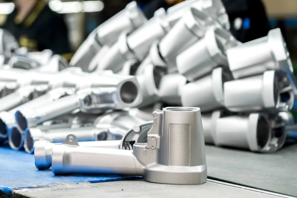
Die casting a pneumatic tool housing begins with a CAD review at the quoting stage, where draft, wall sections and gating are agreed before the mold is cut. Part size determines machine selection, ADC-12 covers most tool housings, and features such as bores and mating faces are machined afterward instead of cast to size.
JoinCast has been casting aluminum in Changhua, Taiwan since 1987, and die cast pneumatic tool components are among the parts we run most often: housings, valve bodies, end caps, trigger mechanisms and motor chambers for nailers, impact wrenches, grinders and spray guns. Twelve die casting machines from 135 to 900 tons are housed in the same 9,900 square meter plant as 49 CNC machining systems and our surface treatment lines. All figures here are as of August 2026.
What does a die casting supplier check on a pneumatic tool housing drawing?
Our mold engineering team reviews your CAD files during the quoting phase and returns DFM recommendations on draft angle, wall thickness uniformity and gate placement. Nine mold engineers perform this review, using Solidworks and Siemens NX, with mold flow simulation to predict fill patterns, size gates and runners, and confirm that the cooling channels perform as intended.
Draft angle and parting line on a split tool housing
A tool housing that splits into two shells gives you a natural parting line, though the natural line and the best one for casting aren’t always the same. Where the split runs across a curved grip section, parting line placement determines how much flash sits on a surface the operator holds. We examine this first, together with the draft carried on internal ribs.
Wall thickness for an aluminum die cast housing
Our typical section for aluminum die castings runs 2.5 to 4.5 mm, with 1.5 mm as the practical minimum and around 15 mm at the top end. A thick section behind a boss or a mounting pad won’t cool at the same rate as the wall around it, so flag it early. Where the drawing shows a heavy section that a rib would serve equally well, we’ll say so during the review, well before the tool is running.
Gate placement and cosmetic surfaces on a tool housing
We choose gate position to keep visible marks off cosmetic surfaces and defects out of functional areas. On a pneumatic tool this usually means gating into a face that later disappears under a grip, a label or a mating component. We can’t tell from the model alone which faces are cosmetic, so mark them on the drawing.
Machining stock and datum features
Leave stock where a datum feature will be machined, and say which features carry the datums. There isn’t one allowance that suits every feature, so treat this as advice rather than a rule. A drawing that shows the datum scheme lets us fixture the part properly the first time.
Which die casting machine suits your pneumatic tool housing?
Part size determines machine selection, and our range covers parts up to 700 mm on the 900 ton machine, with weights of 5 grams to 3 kilograms. The smaller machines take proportionally smaller parts: up to 150 mm on the 135 ton, 200 mm on the 180 ton, 300 mm on the 250 ton, 350 mm on the 350 ton and 400 mm on the 420 ton.
Automation and process monitoring during die casting
Fanuc robotic arms handle extraction, and six-axis arms perform ladling and metal injection, which keeps shot conditions consistent across a two-shift day. We monitor temperature, injection pressure and cycle timing during production, and we log the measurements for traceability. You can read how that process monitoring during casting works in practice.
ADC-12 and A360 for pneumatic tool housings
We run ADC-12 / A383 and ADC-3 / A360. ADC-12 covers most pneumatic tool housings, and A360 is specified where corrosion resistance and ductility matter more than castability. Where the naming creates confusion, and you’ll see a JIS designation on a Taiwanese quotation against an ASTM designation on a European drawing, we keep a reference on ADC-12 and its regional equivalents, and a longer piece on aluminum die casting alloy selection. Compositions are specified in ASTM B85/B85M-25.
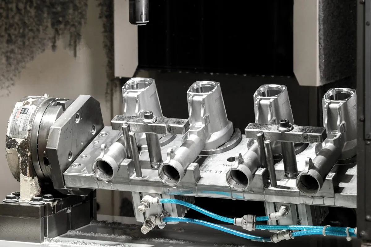
Which features are die cast, and which are CNC machined?
As-cast surfaces hold ±0.15 mm and an as-cast finish of Ra 3.2 to 6.3 micrometers, while bores and mating faces are machined to H7 where the drawing calls for it. General tolerances for the cast condition follow ISO 8062-3:2023, and NADCA’s product specification standards separate standard from precision tolerance grades, a distinction worth resolving before quotation.
Datum scheme for cast and machined features
The casting has one datum scheme and the machined part usually has another, and the two have to reconcile. Where the drawing leaves that open, we’d rather ask at the quoting stage than assume. We design and build our own fixtures, and the same building holds the die and the fixture, so the reference surfaces we pick for machining are chosen against the tool geometry we already know. On a housing with a bore that must stay concentric with a cast boss, this determines whether the drawing is achievable at volume.
CNC machining capacity for die cast housings
Our 49 CNC systems include 14 OKUMA horizontal lathes and 33 FANUC vertical machining centers, and every machine carries a fourth axis, which matters on a housing that needs boring, threading and tapping on more than one face. The machining hall is temperature controlled to hold dimensional stability. For high-volume orders we keep statistical process control documentation, and because we machine cast housings in house, the team that cast the part also measures it, so a dimension that drifts is found in the same building.
Dimensional inspection of die cast tool housings
We perform CMM sampling and 3D scanning at defined intervals during production. First article inspection uses two Mitutoyo CMMs and a Keyence 3D scanner comparing scan data against your CAD model, and the inspection system resolves to 0.002 mm, comfortably finer than the tolerances it verifies. We inspect every part visually before packing, and a ten-person quality team runs first article and dimensional inspection through the whole build.
Cast and machined features on a pneumatic tool housing
| Feature on a tool housing | Cast or machined | Controlled by | Verified by |
|---|---|---|---|
| External housing profile | Cast | Tool design, draft angle | 3D scan against CAD |
| Mating face flatness | Machined | Fixturing, datum scheme | CMM |
| Valve or bearing bore | Machined to H7 | CNC, fourth axis | CMM |
| Internal chamber wall section | Cast | Tool design, mold flow simulation, process monitoring | First article inspection |
| Grip area cosmetic surface | Cast, then finished | Gate and ejector placement, surface treatment | Visual inspection, roughness tester |
| Corrosion resistance of the finish | Finishing | Coating selection | Salt spray testing |
Surface treatment and first samples for die cast tool housings
Surface treatment, polishing, shot blasting and grip overmolding all take place in the same plant, so the component arrives ready for your assembly line.
Surface treatment options for aluminum die castings
We apply powder coating, liquid coating, electro-coating, anodizing and SurTec 650 trivalent chromium treatment in house, and we verify corrosion resistance with salt spray testing. Eight polishing machines and three shot blasting systems handle the mechanical finishing. Which coating suits a given tool depends on how it’s stored and handled in service, so tell us where the tool will be used and we will recommend a suitable coating.
TPR grips overmolded onto the casting
Where a housing carries an overmolded grip, we mold the TPR onto the casting in the same plant, so the aluminum doesn’t leave the site between operations. The TPR grips overmolded onto the casting article covers the material and bond side of that work.
First samples and tooling lead time
We design, build and sample a new tool in around 65 to 90 days before the first approved parts. We send samples with the inspection record, and we verify alloy composition on our spectrometer, which returns an elemental analysis in about 60 seconds. What you’re approving at that point is the tool as much as the part, so changes to draft, rib layout or gate position are worth raising then, while alterations to the steel remain inexpensive.
Our molds stay in our facility for their service life, which keeps maintenance, repair and any later modification with the team that built them.
Frequently asked questions about pneumatic tool housing die casting
What do you need to quote a pneumatic tool housing?
JoinCast quotes from 3D data, and a 2D drawing showing tolerances, datums and cosmetic faces makes the quotation more accurate. Annual volume and the target alloy help us match the part to a machine and estimate tooling. Our mold engineering team reviews the CAD file during quoting and returns DFM feedback with the quotation.
Will you tell me if my draft angles or wall sections need changing?
Yes. JoinCast mold engineers review customer CAD files at the quoting stage and recommend changes where a section, a draft angle or a gate position will create problems in the tool. We run mold flow simulation to check fill patterns and cooling before we build the mold. Raising a change at that point costs far less than modifying a hardened tool later.
Which features do you machine rather than cast?
Bores, valve seats, mating faces and threaded features are machined, since as-cast surfaces at JoinCast hold ±0.15 mm while machined features can be held to H7. Cast features carry the external profile, ribs, bosses and general form. Deciding which is which at the drawing stage keeps the tolerance stack sensible and avoids unnecessary machining.
What part sizes and weights can you die cast?
JoinCast runs twelve die casting machines from 135 to 900 tons, covering parts up to 700 mm and weights of 5 grams to 3 kilograms. Typical wall sections are 2.5 to 4.5 mm, with 1.5 mm as the practical minimum. Machine selection follows part size and part weight.
Which surface treatments can you apply in house, and how is the finish checked?
JoinCast applies powder coating, liquid coating, electro-coating, anodizing and SurTec 650 trivalent chromium treatment on automated lines in Changhua, with eight polishing machines and three shot blasting systems for mechanical finishing. Salt spray testing verifies corrosion resistance, so the finish isn’t signed off on appearance alone. Keeping finishing in house means one company is responsible for the casting, the machining and the coating.
How long does tooling take for a new tool housing?
JoinCast designs, builds and samples a new tool in around 65 to 90 days before the first approved parts. The exact schedule depends on the size, tonnage and complexity of the mold. Molds remain in our Changhua facility for their service life, so maintenance and later modifications stay with the team that built them.