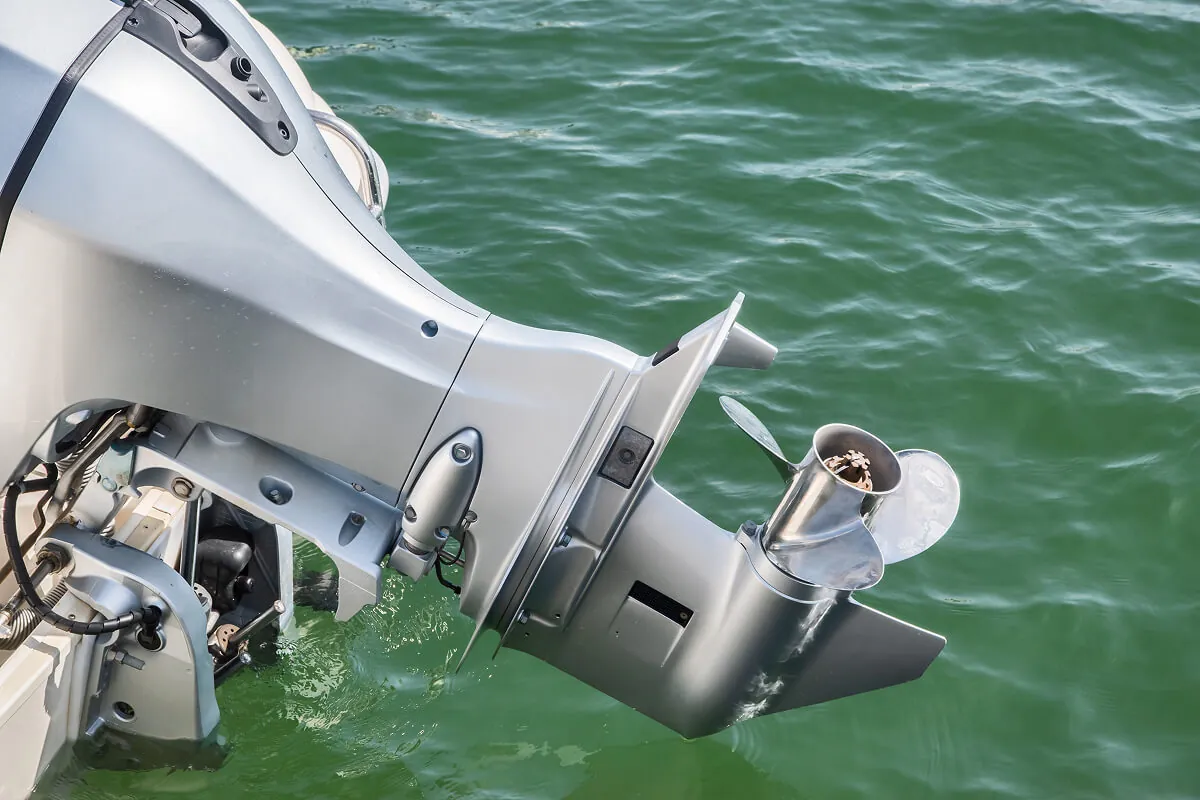
Outboard motor die casting at JoinCast covers aluminum gear cases, extension housings, shaft housings and engine mount housings. JoinCast recommends designing these parts to a typical wall section of 2.5 to 4.5 mm, a draft angle of 1.5° to 3° and corner radii of at least 0.5 mm, and machines bearing seats and mating faces where the drawing requires it.
JoinCast is a vertically integrated aluminum die casting manufacturer in Changhua, Taiwan. Marine component die casting is one of the sectors we serve, and a good deal of that work is for outboard motors. In this article we show four families of outboard motor components we’ve produced and explain the design recommendations our engineers apply to parts like them, so that you can see what we’d look for when we review your own drawing. Figures here are current as of September 2026.
Outboard motor components we die cast
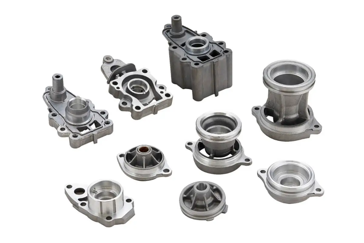
We die cast gear cases, extension housings, engine mount housings and shaft housings for outboard motors, and we work primarily with ADC-3 and A360 for marine applications. The compositions of these alloys are specified in ASTM B85/B85M-25, the ASTM International specification for aluminum-alloy die castings. The photographs in this article show parts from our own production.
Gear cases and extension housings
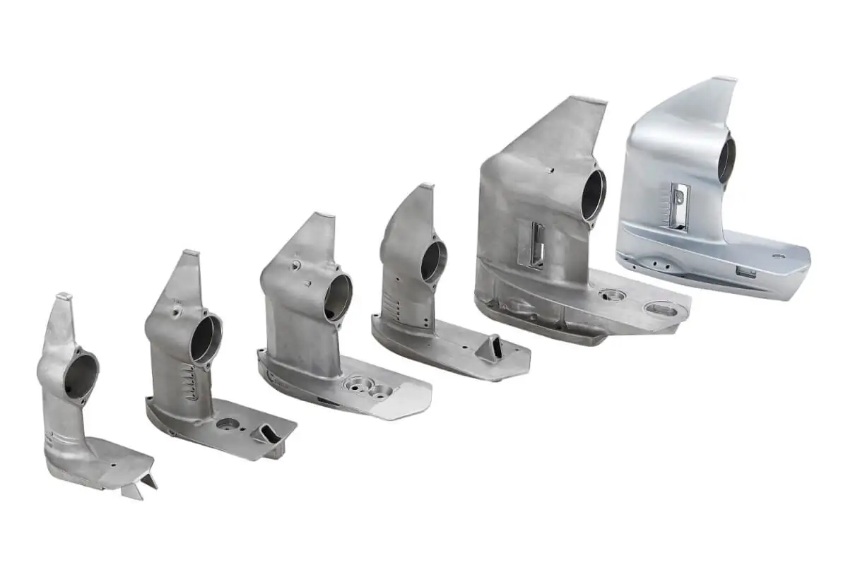
The gear cases we produce carry their main bore, the intake slots and the skeg in a single casting, and the photograph shows five of them as cast and one after finishing. Seen together, the range shows how the same cast features are carried across all six sizes.
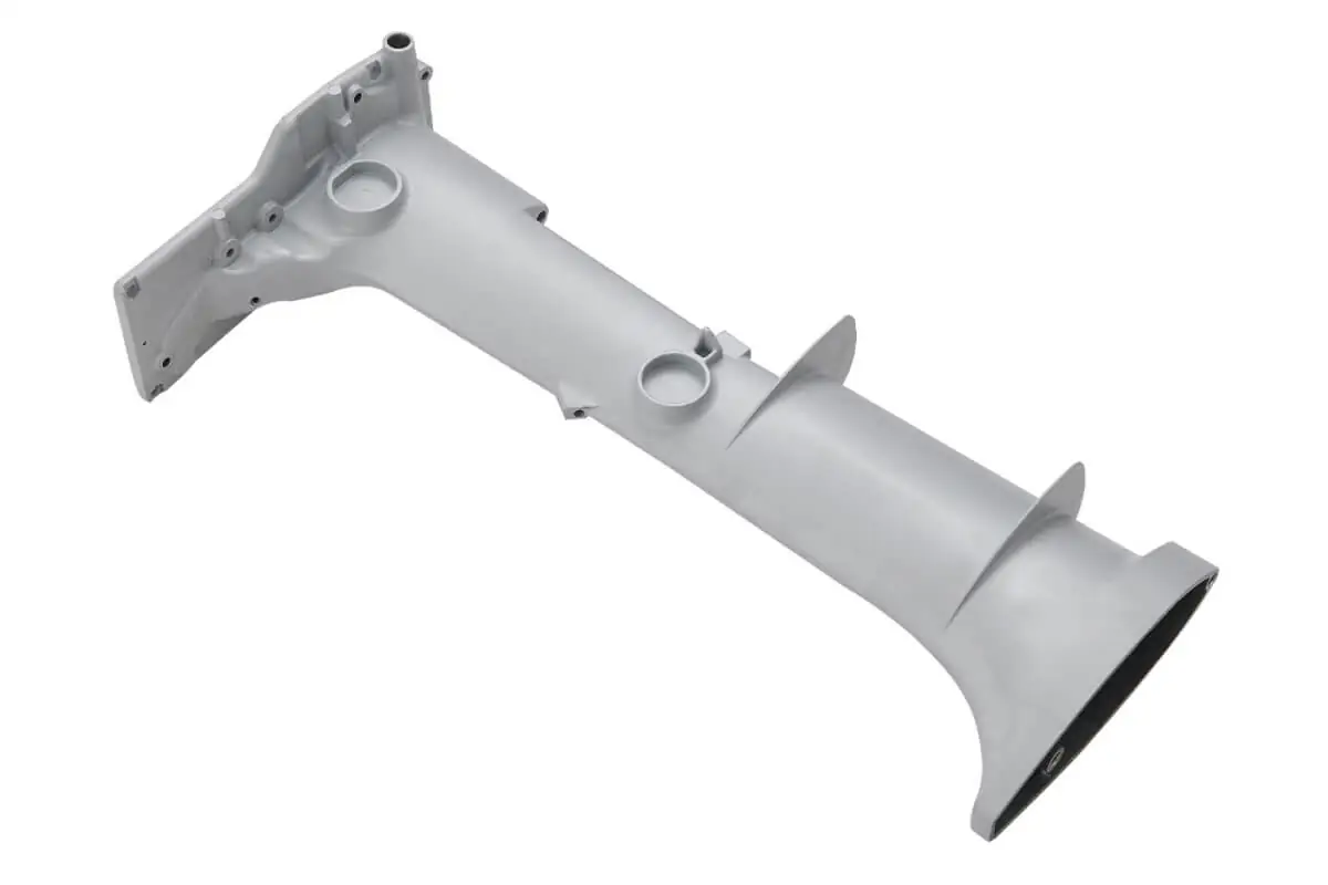
The extension housing is a long tubular casting with a mounting flange at the upper end, cast bosses along its length and a flared lower end, and it’s shown here after finishing. On a part of this length the metal travels a long way from the gate, which is why the flow path matters as much as the wall section itself, and we return to this point below.
Engine mount and shaft housings
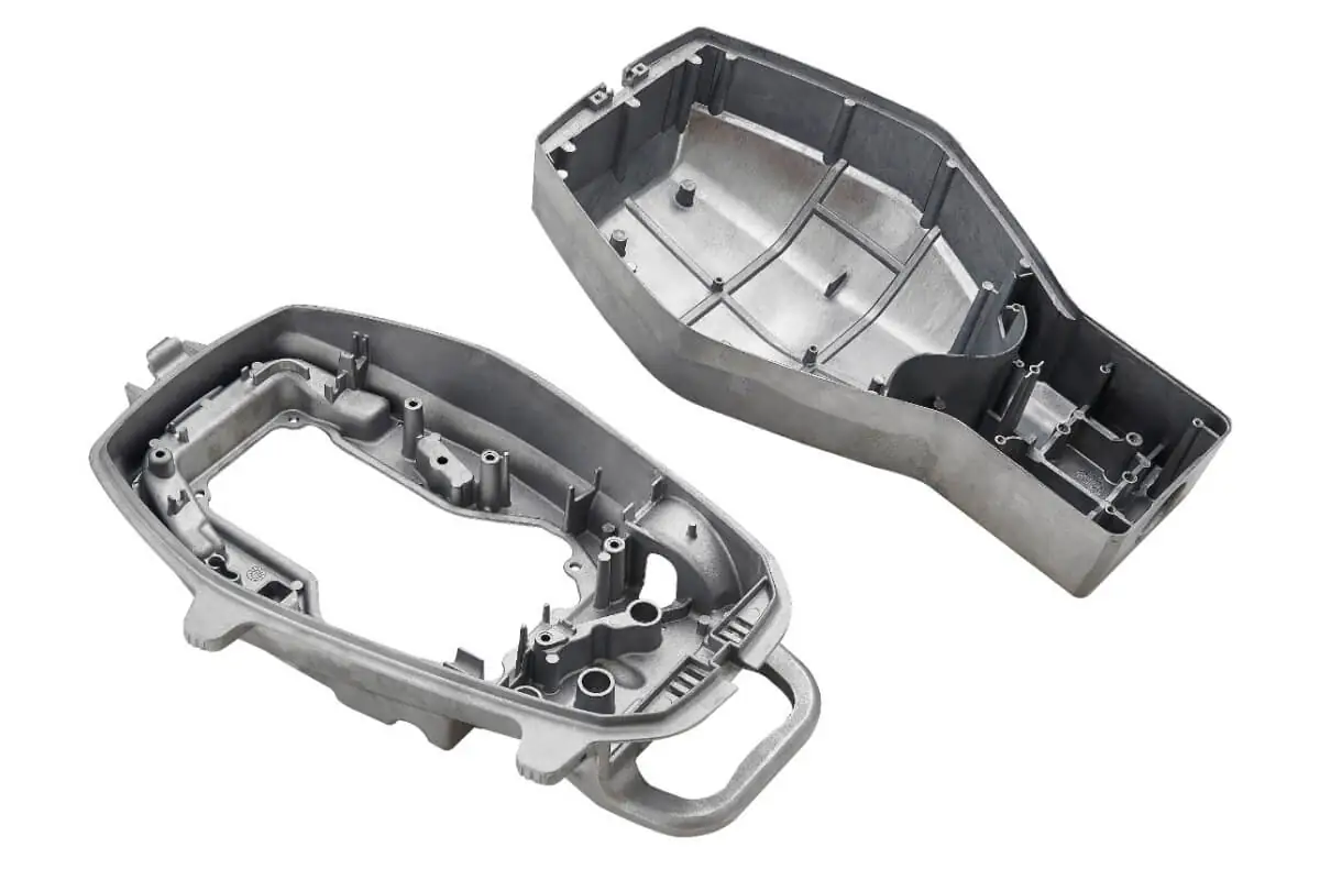
The engine mount housings are two large open shells. Both are reinforced by a network of internal ribs, carry a large number of screw bosses, and one has a carrying handle cast integrally with the shell. These parts show the approach we recommend for adding stiffness, which is to use ribs in place of a thicker wall.
The shaft housings are a set of nine smaller parts in different sizes, most with a two- or three-hole mounting flange. Their bores and seats are machined after casting, and you can see the machined surfaces as the bright rings in the photograph. Several carry external ribs, and one is shown with a bushing fitted.
Design recommendations for die cast outboard motor housings
Our engineers apply the same set of design recommendations to every outboard motor casting, and our mold engineering team reviews your CAD files during the quoting phase and provides DFM (design for manufacturing) feedback against them. We also use mold flow simulation to identify potential defects before we begin building the mold.
Wall thickness and metal flow
We recommend a wall thickness of 2.5 to 4.5 mm, with a maximum of 15 mm. The minimum is 1.5 mm, and we’d suggest keeping walls that thin to feature detail or to parts under 50 mm. Uniform wall thickness matters a great deal in die casting. Where the wall varies considerably, different sections need different cooling times and shrink by different amounts, and that uneven solidification can leave internal stresses, shrinkage porosity and other defects. An excessively thick section may also show sink marks on the surface and contain gas or shrinkage porosity when it’s sectioned.
Sections near the gate can be made slightly thicker. Farther from the gate, the metal shouldn’t have to pass through a thin section and then into a thicker one, because this can cause poor filling, premature solidification and increased porosity. On a long part such as an extension housing, we would suggest checking the path from the gate to the far end of the casting before you settle the wall sections.
Ribs in place of thicker walls
Where a part needs more strength or stiffness, we recommend adding ribs instead of increasing the wall thickness. The engine mount housings above are a good example of this approach. Each rib should have fillets at its base and in the surrounding areas, which reduces stress concentration and improves metal flow and solidification.
Draft, radii and edges on outboard motor castings
We recommend a general draft angle of 1.5° to 3°, with a minimum of 0.5°. Corners should carry a radius of at least 0.5 mm wherever this is feasible, and sharp edges should be avoided.
Draft angles on the fixed and moving die halves
When features on the fixed-die side and the moving-die side are symmetrical, the draft on the moving-die side can be about half of that on the fixed-die side. We’d suggest making the draft on the fixed-die side as large as is practical. This helps the part release, and it makes sure the casting stays on the moving-die side when the die opens. For the same reason, internal holes and related features are better placed on the moving-die side where the design allows it. These points are worth settling at the drawing stage, since they’re much easier to change on a drawing than in a finished mold.
Corner radii and sharp edges
Sharp corners shorten die life and can cause cracking at the corners of the casting, so we recommend rounded corners and fillets wherever possible, with a radius of at least 0.5 mm. Sharp edges carry two further risks. Gas, lubricant vapor and cold metal can collect at a sharp edge and cause defects in the casting, and the edge itself is easily damaged by impact, chipping or deformation during handling, machining, assembly and transport. On an outboard motor casting, thin features such as the skeg of a gear case deserve particular attention on this point.
| Design feature | Our recommendation | Reason |
|---|---|---|
| Wall thickness | 2.5 to 4.5 mm, kept as uniform as possible | Even cooling and shrinkage, fewer internal stresses and less porosity |
| Maximum wall | 15 mm | Thick sections risk sink marks and gas or shrinkage porosity |
| Minimum wall | 1.5 mm, in feature detail or parts under 50 mm | Thinner walls are harder to fill |
| Flow path | No thin section feeding a thicker one far from the gate | Avoids poor filling, premature solidification and porosity |
| Draft angle | 1.5° to 3°, minimum 0.5° | Part release; casting stays on the moving-die side |
| Moving-die draft | About half the fixed-die draft where features are symmetrical | Fixed-die side kept as large as practical |
| Internal holes | On the moving-die side where possible | Keeps the casting on the moving die at opening |
| Corner radii | At least 0.5 mm wherever feasible | Longer die life, no cracking at corners |
| Stiffness | Ribs with fillets at the base, not thicker walls | Less stress concentration, better flow and solidification |
| Edges | No sharp edges | Fewer trapped-gas defects, less handling damage |
Machining, finish and inspection on marine outboard motor components
Porosity and variation in material properties are inherent risks in aluminum alloy die casting, so we recommend building an adequate design safety factor into every structural outboard motor part. This allows for possible variation in material strength and casting quality, and it gives the part the reliability it needs in service.
Machined features and the design safety factor
As-cast surfaces typically hold a tolerance of ±0.15 mm, and we machine bores and mating faces to H7 where the drawing requires it, as on the shaft housings shown above. All 49 of our CNC machining systems have fourth-axis capability, which is useful on a gear case or a housing that needs machining on more than one face. Your parts go from die casting through CNC machining to surface treatment within our Taiwan production facility, so the part stays within one facility between operations.
We’d suggest setting the safety factor alongside the wall, rib and radius recommendations above, since those reduce the porosity that the safety factor has to allow for, and it’s easier to do both at the drawing stage.
Finish, corrosion testing and first article inspection
We run fully automated surface treatment systems in house, covering powder coating, electro-coating, liquid coating, anodizing and SurTec 650 trivalent chromium treatment. Our quality team conducts ASTM B117 salt spray testing to validate corrosion resistance, typically for 96 to 500 hours on marine components. ASTM notes that B117 does not prescribe the exposure period for a specific product or the interpretation of the results, so we’d suggest agreeing the hours and the pass criteria with us before we cut the tooling.
Before production, our quality team carries out a complete first article inspection with two Mitutoyo CMMs (coordinate measuring machines) and a Keyence 3D scanner, which compares the part against your CAD model.
If you have an outboard motor component in development, please get in touch and send us the CAD file with your drawing, and we’ll review it against the recommendations above. Our article on what we check on a housing drawing explains that review in more detail, and our guide on how to source die cast components covers tooling, quotations and terms.
Frequently asked questions about outboard motor die casting
Which outboard motor parts does JoinCast die cast?
JoinCast die casts aluminum gear cases, extension housings, engine mount housings and shaft housings for outboard motors. JoinCast works primarily with ADC-3 and A360 for marine applications, and machines and finishes the parts at its production facility in Taiwan.
What wall thickness do you recommend for an outboard motor casting?
JoinCast recommends a wall thickness of 2.5 to 4.5 mm for outboard motor castings, kept as uniform as possible, with a maximum of 15 mm. A minimum of 1.5 mm is suitable for feature detail or for parts under 50 mm. Where more stiffness is needed, JoinCast recommends adding ribs rather than thickening the wall.
What draft angle should an outboard motor housing carry?
JoinCast recommends a general draft angle of 1.5° to 3° on outboard motor housings, with a minimum of 0.5°. Where features on the two die halves are symmetrical, the moving-die side can carry about half the draft of the fixed-die side, which helps the casting stay on the moving die when it opens.
Do you machine and finish outboard motor components in house?
JoinCast machines and finishes outboard motor components in house, from die casting through CNC machining to surface treatment. As-cast surfaces typically hold a tolerance of ±0.15 mm, and bores and mating faces are machined to H7 where the drawing requires it.
What corrosion testing do you apply to outboard motor castings?
The JoinCast quality team conducts ASTM B117 salt spray testing to validate corrosion resistance, typically for 96 to 500 hours on marine components. ASTM B117 does not set the exposure period or the pass criteria for a product, so it’s worth agreeing both with JoinCast before tooling begins.